Topic: Steady Loading and Failure Theory
Subject: Machine Design
Tool: Scilab
A static or steady load is a stationary force or moment acting on a machine or structural member. There are two approaches to calculate the margin of safety to prevent failures on the member: - factor-of-safety (\({FoS}\)) and reliability approach. These examine or compare the strength of a member and the anticipated induced stress from static loading for the selection of the optimum or suitable material and dimensions.
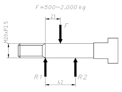
This article demonstrates the use of \({FoS}\) approach in verifying the suitability of a machine member for the given steady load. Figure 1 illustrates the condition in which the T-bolt made of AISI 1050 will be used as shackle pin to carry or lift a range of steady load from 500 to 2000 kg. The \(FoS\) approach can determine the maximum dead load the pin is capable of lifting steadily.
Equations (1), (2), and (4) represent the basis for calculating \({FoS}\) from the given condition.
\({FoS}\) in Simple Tension, Compression, or Bending
$${FoS}_{bending}\;=\;\frac{\sigma_{yp}}{\sigma_{max}} \tag{1}$$
\({FoS}_{bending}\) – factor-of-safety in simple tension, compression, or bending
\(\sigma_{yp}\) – material’s yield point
\(\sigma_{max}\) – maximum induced stress
\({FoS}\) in Pure Shear
$${FoS}_{shear}\;=\;\frac{\tau_{yp}}{\tau_{max}} \tag{2}$$
\({FoS}_{shear}\) – factor-of-safety in pure shear
\(\tau_{yp}\) – material’s yield point in shear
\(\tau_{max}\) – maximum induced shear stress
\({FoS}\) using Max Shear Stress Theory
$$\tau_{mss}\;=\;\sqrt{\left(\frac{\sigma_{max}-\sigma_{min}}{2}\right)^2 + \tau_{max}^2} \tag{3}$$
$${FoS}_{mss}\;=\;\frac{\tau_{yp}}{\tau_{mss}} \tag{4}$$
\({FoS}_{mss}\) – factor-of-safety based on maximum shear stress theory
\(\tau_{mss}\) – induced stress using max shear stress theory
\(\sigma_{max}\) – stress due to bending at outermost surface of the shackle pin
\(\sigma_{min}\) – stress due to bending at neutral axis of the shackle pin
For steady loading, the recommended factor-of-safety is from 1.5 to 3.0 for the general engineering applications and ductile materials. The use of 1.5 as factor-of-safety will determine the maximum allowable steady load for a member. Presented below is the Scilab script for calculation documentation and validation of design in a typical engineering organizational setup.
Scilab Script
// Copyright (C) 2025 - Gani Comia
// Date of creation: 7 Feb 2025
// Shackle Pin Stress Analysis Rev 01
clear;clc;

// (1) Primary and secondary parameters.
d = 17.5;               // mm, minor dia for M20 thread
L = 42.0;               // mm, length under load
Wt = 500:10:2000;       // kg, weight of load
F = Wt.*9.8;            // N, load per pin
A = (%pi/4)*d.^2;       // mm^2, cross-sectional area at thread
S = (%pi/32)*d.^3;      // mm^3, section modulus of pin

// (2) Maximum moment and shear load.
Mmax = F.*L./4;         // N-mm, max moment load
V = F./2;               // N, max shear load

// (3) Bending and shear stress.
sigmaMax = Mmax./S;     // MPa, max bending stress
tauMax = (4/3)*V./A;    // MPa, max shear stress

// (4) Material properties, AISI 1050
sigmaYp = 375.0;        // MPa, yield point
tauYp = 0.5*sigmaYp;    // MPa, yield point in shear

// (5) Factor-of-safety (FoS), Bending and Pure Shear
FoSbending = sigmaYp./sigmaMax;     // factor-of-safety in bending
FoSshear = tauYp./tauMax;           // factor-of-safety in pure shear

// (6) Factor-of-safety (Fos), Max Shear Stress Theory
sigma1 = sigmaMax;          // MPa, max principal stress, outermost
sigma3 = 0;                 // MPa, min principla stress, neutral axis
tauMss = sqrt(((sigma1-sigma3)/2).^2 + tauMax.^2);  // MPa, MSST
FoSmsst = tauYp./tauMss;    // factor-of-safety in max shear stress

// (7) Plot of analysis
clf;
plot("ln",Wt,FoSmsst,"b-","linewidth",3);
plot("ln",Wt,FoSbending,"r--","linewidth",1.5);
plot("ln",Wt,FoSshear,"m-","linewidth",2.5);
note1 = ["Max Shear Stress","Bending Stress","Shear Stress"];
legend(note1,with_box=%F);
xgrid(3,0);
title("Shackle Pin FoS based on Failure Theory","fontsize",3.5);
xlabel("Lifting Load [kg]","fontsize",3);
ylabel("Factor of Safety","fontsize",3);

// Interpolating weight for the min factor-of-safety 1.5
format(6);
fos = 1.5;
wtInt = interp1(FoSmsst,Wt,fos);
disp(fos, wtInt);
xVerMin = [wtInt wtInt]; xHorMin = [400 wtInt];
yVerMin = [0 fos]; yHorMin = [fos fos];
plot(xVerMin, yVerMin,"b--");
plot(xHorMin, yHorMin,"b--");
plot(wtInt, fos,"marker","s","markerFaceColor","blue");
note2 = ["Max Load (kg) =",string(wtInt),"@ FoS =",string(fos)];
xstring(wtInt-50,fos+0.4,note2);
note3 = "https://gani-mech-toolbox.blogspot.com";
xstring(1200,11,note3);
Scilab Script Output (Figure 2)
Figure 2. Plot of Calculation of the Three Failure Theories.
The resulting plot shows that for a minimum factor-of-safety of 1.5, the shackle pin should only be loaded with not more than 1232 kg to prevent failure.
Feel free to comment for inquiry, clarification, or suggestion for improvement. Drop your email to request the soft copy of the file.
Disclaimer: The formulas and calculations
presented are for technical reference only. Users must verify the accuracy and
ensure compliance with applicable engineering standards, codes, and safety
requirements before practical application.


No comments:
Post a Comment